Sunday 9 July 2017

3D printer adventure return

I have not been engaged in 3D printing activity for like 4 to 5 years.  And there is significant development in DIY 3D printing space.  Here are some of my observation so far:

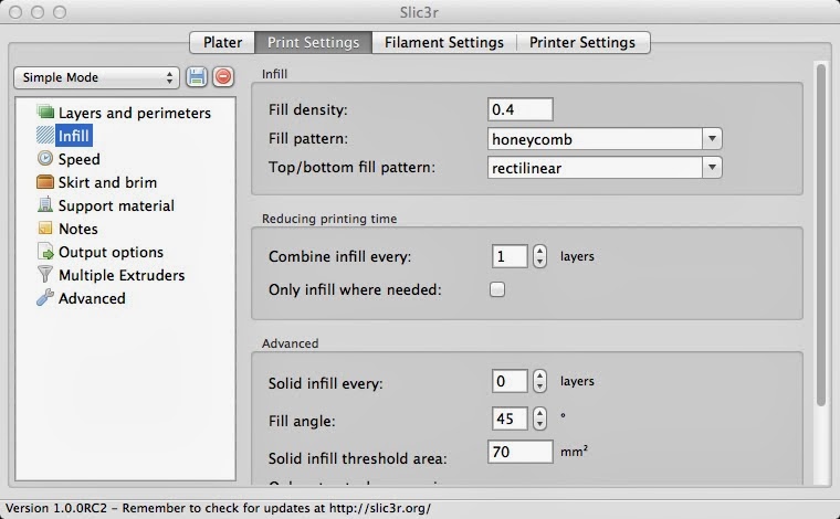
  • GUI based slicer is become popular. CURA have gain a lot of traction. 
  • 24V is now standard.
  • Print quality have improved significantly thank to better print head design.
  • Quality of China clone part have improved significantly, now you can get 100% clone Ultimaker for less than 400USD.
  • CoreXY seem to more popular printer type, and delta design for large printer design are common.
  • In heated bed, PEI sheet bed seem to be really popular, follow by glass bed with glue stick.
  • Auto leveling moving toward touch for glass bed and inductive sensor for aluminum bed.  
  • More printer bed design is now bigger then 200x200, 300x300 are getting common. 
  • Print height also getting taller. 


So, after all this finding, what kind of printer that will build for myself?  Here is first draft spec:
  •          Build size: 300x600x900
  •          CoreXY design
  •          Dual Z support
  •         2 to 3 all metal independence print head
  •          Glass heated bed with touch sensor
  •        32bit controller
  •          24V design
  •          3030 aluminum extrude frame

Actually, I wanted to build a printer of 1000x1000x1000, but in really, we may not need the large print size, and due to cost reason and difficulty to find parts, it seems to be more achievable to go with 300x600x900 design since all part are ready available.  Cost is lower if you can easily find part.

For CoreXY, seem like it currently the prefer method, maybe will go to more traditional design later.

Dual Z because it makes the print bed more stable.
  
Large print size brings another problem, print time, even with large nozzle size like 0.1mm, it still takes significant amount time to print, but if you can add more extruder, it will reduce the print time by number of extruder, the question is how does slicer support this? Software is a major concern.

Why glass, because glass have better flatness compare to metal.  Still considering should go with aluminum bed heater since it very common to find 300x330 print bed or just go with silicon heated bed.

32bit controller is no brainer, 24V is also standard now.

Rigid frame is importance for good printer, 3030 is good for frame, and is locally available.

Wednesday 17 December 2014

How to build Yocto RT for Minnowboard Max Drone


Before you begin, it good idea to read through Yocto getting started guide.  And we assume you are using Ubuntu.

How to build Yocto for Minnowboard Max drone:

1) Install require tool/software for Yocto build:


sudo apt-get install gawk wget git-core diffstat unzip texinfo gcc-multilib build-essential chrpath socat libsdl1.2-dev xterm

2) Download Yocto and meta-intel:


mkdir maxdrone
cd maxdrone
cd poky
git clone git://git.yoctoproject.org/meta-intel


3) Setup build directory

cd ..
source poky/oe-init-build-env mybuild
  
 4) Add meta-intel path to  bblayers.conf

vi conf/bblayers.conf

add “/home/<user>/maxdrone/poky/meta-intel \”to BBLAYER section like below:


5) Add platform,  RT and Linux version to local.config.


vi conf/local.conf

And add this line to the end of the file:

MACHINE ?= "intel-corei7-64"
PREFERRED_VERSION_linux-yocto = "3.14%"
PREFERRED_PROVIDER_virtual/kernel = "linux-yocto-rt"

      6) Create local Linux kernel for Kernel or driver customization (skip if not build for debug):


bitbake linux-yocto -c kernel_configme -f
bitbake linux-yocto -c menuconfig

You will see a menu like this, make sure you save and then exit if you are making change to the configuration.


7) Build the image, we use sato sdk.  Other image like “core-image-sato” if you are done with development.  Also if you want build with yoction image with UI interface, try “hop” command instead of "bitbake".


bitbake core-image-sato-sdk


8)      Once the OS image is build, it will be store in <Build Dir>/ tmp/deploy/images/intel-corei7-64, and we use dd to write to USB drive.  You can use df to quickly search for the usb drive located, our case, it at /dev/sdc.


Then use DD to write to USB drive:

sudo dd if= core-image-sato-sdk-intel-corei7-64.hddimg   of=/dev/sdc

Wait until the light on the USB drive stop blinking.  Now you have a Yocto RT USB drive. 

Have fun.

Tuesday 9 December 2014

Kicad on Win7

Recently I created a PCB for the drone project that I'm working on and I would like to share my experience with Kicad for PCB creation.


Above is the finish PCB design that I send for fabrication this afternoon, will post the PCB photo once I got my PCB back from China, hopefully by next week.


First, you need to download the kicad for window,  I use this version from:

http://kicad.nosoftware.cz/

The latest build I can find on net is default stable version is 2013, which does not have the latest interactive routing.  I wish they could update the stable version to late 2014 build..

Just download from the latest version.  I found it to be really stable, no crash so far (after I fix the really annoying PCB footprint library)


Once you install kicad on window, you should copy the PCB footprint library to local disk, default is getting the library from github, which is really slow, and some time cause crash (I think someone fix the github path crash issues, it use to point to some path that is no longer exist).

There is python script that will download all the github library to local disk. But the posted version seem to be have error in it, will post my version later.  You can read about the frustration of using the footprint library here

Basically, you need to download all the footprint library to local disk, here is the step
  1. Download library using git from python script. (script to be send out later, make sure you install git and python in your PC)
  2. Copy fp-lib-table.for-pretty from C:\KiCad\share\template to C:\Users\<user>\AppData\Roaming\kicad as fp-lib-table
  3.  create or update runkicad.bat with  KISYSMOD to local disk. SET KISYSMOD=C:\kicadlib\kicad\share\github-repo <your local area>

Now you need to start kicad with the bat file, so that it will point to the local library.

Kicad schematic editing is really easy, just open a new project start creating.  Here is example of my drone schematic.


Just place and round the schematic, and sometime you may need to design your schematic symbol, which also very easy in kicad. the library editor is really easy to use too, just open an existing symbol, make change and save as your new symbol.


Once you are done with schematic design, the next stage is to create netlist for PCB as well as assigning footprint, it done using another tool call CvPCB.


Once you are done with footprint assignment, you move to PCB design.   We base our board design base on MinnowBoard Max lure.  you can import the board outline easily, and the Minnowvoard Max board design file is freely downloadable. (pointer to be update later)

Before start editing in PCB, you need to set few more thing, one is the PCB design rule, you need to review you PCB manufacture design rule and update you kicad design rules accordingly.   Normally they display the rule at front of the order page, here is the example PCB  rule found on ebay:

Here is where you set the rule in kicad (Design Rules --> Global Design Rules):


Also you may want to create wide wire for power or some net that need wide track, it better to do this before starting routing, else you need to use "change segment/track width" canvas pulldown menu to change the wire width.

To create wide wire, go to Design Rules --> Net Class Editor.  First by adding a new net classes in the window, then select the newly create net class in the pull down menu on the right of membership. You just add and remove the net from the net class.   


OK.  Once you are done with the design, you need to generate and send the gerber to PCB manufacture for review and quote.   Normally they will comeback with some request if there is problem.  Below is our gerber output setting that our PCB manufacture requested after some feedback from them.  Our board is 2 layer design:


Also you will generate a drill file as well, and here is our setting:


 As always, you should review your gerber file before sending for fabrication. Any mistake will be costly.  Here is our final design view in gerber file viewer provided by kicad.


This my quick update on how to setup and use kicad on window platform.  Hope you enjoy it..


Saturday 26 April 2014

BeagleBone Black Linuxcnc with RAMPS 1.4 (part 1)

Recently I saw a news about using BBB connect to RAMPS-FD with LinuxCNC,  But problem is the RAMPS-FD is  still expensive compare to RAMPS 1.4.   I say to myself, why not just use RAMPS?


The first thing I do is to look for way to make RAMPS compatible with 3.3v (not sure why I did it, seem like BBB does have 5v tolerance).  There is a detail discussion on how to convert 5v version of RAMPS to 3.3v for Arduino DUE in the Deltabot forum, it very simple hack, basically remove 5v connection from the RAMPS board, and reconnect all of the to 3.3v, then replace the MOSFET that support 5V to 3V input.   Detail of modification could be found here.

I did some cost cutting by replacing PSMN1R1-30L with IRLB8743PBF, it $3.5 vs $1.20, else everything is the same as discuss in the forum. Here is the picture where I remove the MOSFET:


The problem is how to connect BBB to RAMPS, the original design is to RAMPS-FD, and try find a diagram that show the pinout of RAMPS connection to Mega, and I can't!!  It seem like there is no pinout information.  After a lot of googling.... I give up and create the diagram myself.


With that. all I have to do to connect the board with BBB, which I will update in my part 2 of my BBB to RAMPS 1.4 adventure.  Here is the finish board waiting to be connected.


Sunday 6 April 2014

How to get EusLisp compile in Macosx

I was reading about robotic IDE and found this very interesting Japanese robotic development environment call EusLisp.  As usual I just want to play with it.  But it not easy to find information on how to install, seem like it not really popular outside of Japan.


OK.  Here is the step to get it compile:

1) Download the file:

  •      I use this command to get the file from svn, and it base on Trunk R671:
     svn checkout svn://svn.code.sf.net/p/euslisp/code/trunk euslisp-code     
  •      then cd to the lisp directory once it finish downloading:
     cd euslisp-code/EusLisp

     You can checkout the README file included in lisp directory for detail on how to install.. or continue with my description...

2) Setup make/compile environment variable:

  •     In the terminal.  Type in this in the terminal, make sure you are in csh (type csh in terminal to make it c-shell).

   setenv MACHINE x86_64   
   setenv EUSDIR $PWD
   setenv XLIB /usr/X11R6/lib
   setenv PUBBINDIR /usr/local/bin
   cd lisp

3) Edit the makefile and compile file for MacOSX:


  • First link the Makefile.Darwin to Makefile:

    ln -s Makefile.Darwin Makefile
  • update X11 library path to Mac path, I use vi to replace path:
    vi Makefile.Darwin
  • Inside VI run this command to replace the X11 path, original file point to /opt/X11 but in Mac, it in /usr/X11R6:
    :%s/\/opt\/X11/\/usr\/X11R6/g
    :wq
  • Next fix the wrong compile flag in comp/comp.l, it should be -falign-functions but instead it set to -malign-functions :
    vi comp/comp.l

  • Inside VI run this command to replace the error flag:

    :%s/-malign-functions/-falign-functions/g
    :wq

4) Build
    
     make all

Now you can try the build by running this command:

$EUSDIR/Darwin/bin/eusgl


If run successful, you will see this screen in you terminal.


JSK EusLisp have better demo, and the step to fix the build problem is the same.  Include is the JSK EusLisp demo:

Particle Demo


IRT Viewer Demo
Hand Grasp IK Demo


Saturday 1 March 2014

How to install MachineKit BeagleBone LinuxCNC in MacOSX

Recently I wanted to use Beaglebone black for my Chinese CNC 3040 router, trying to installing it is bit complicated.  Here is my learning....

You will not able to use MachinceKit directly because the setup_sdcard.sh script only work on linux. So the first thing you need it todo is to install VMWare.   Once you have the VMware install, you need to install Ubuntu.

Make sure you share your work area in mac to VMWare using the Sharing feature in setting:


Once you share your mac directory to vmware, the director will be located at /mnt/hgfs/<name of directory you share>.

You can't build the image and write to it directly. You need to create the image file in vmware, then write the image to the sdcard manually.

Here is the command I use to create the image file, please note that you need to use the --img-4gb option, the default is 2gb and will not be enough to hold all the file.

sudo ./setup_sdcard.sh  --uboot bone_dtb --img-4gb kk.img

depend on your ubuntu build, you may need to download other program, please read the screen for error message and see if you need to install more program.

Once your image is build, go back to terminal in mac and follow the step to install OS image to usb drive.

Here is my step, please know your location may be difference.


  1. use  df -h to location your usb drive, my usb drive is located at /dev/disk2s1
  2. unmount the usb drive using sudo diskutil unmount /dev/disk2s1
  3. use sudo dd bs=1m if=./kk-4gb.img of=/dev/rdisk2 to write the image to usb drive

Once you done writing the file to usb drive, you will need install the file to beagle bone black, the process of writing and updating beagle bone black take some time.  You will know you are success when you login to your update BBB and see 3.8.13xenomai-bone33 in the login message. 


Or you can run BBB as standalone machine:


Sunday 23 February 2014

What is this 3D slicer program? - Part 2

My favorite slicer program is Slic3r, it have one unique feature that other don't have, ability to set honeycomb fill pattern, it really a strong and beautiful structure.   Here is picture of the pattern.


There is also one other feature that you may want to turn on is the brim feature, it the extra printed line at boundary object you are printing.  The main purpose is to extrude the first few inch of plastic so that it have a better consistency when printing actual object. See the picture below:


 Let get start on how to setup you slic3r, first you need to download the program from here.

 Once you download the software and run it, you will see setup screen:


Next is to select the Firmware type, if you using the diy reprap, it should be "RepRap (Marlin/Sprinter/Repetier)" unless you use other firmware.


Next is to set the print bed size.   Normal is 8"by 8" or 200 by 200mm.


Next is to set the Nozzle diameter, for my case, I use 0.35mm.  Make sure you are setting to the right number.


Next is to set the filament Diameter. it either 1.75mm or 3mm.


Next is Extrusion Temperature.   You may need to play with this number later on.  I use 240c for ABS.   Note that this may melt your hotend if you are not careful.   Buy full metal hotend if possible. J-head is just too much pain if you using ABS.


Next is to setup the heat bed temperature.   I use 100c for ABS, but sure to use Kapton tape so that it help part stick well to the bed.   Will go into detail in one of my future post.  


You have setup your printer!!


Once you have it setup, you can drag a object to your work area.  It just have the outline of area use in the printer and to see the model in 3d, just click on the View panel.


Will go through the detail setting in my next update, for now, I'm going to show you where you set the print fill structure setting.  Goto "Print Settings" --> Infill --> Fill pattern, select "honeycomb"


And for the brim, goto "Print Setting" --> "Skirt and brim" --> "Brim width".  Just use 2mm.


I hope you like this work through, next I will go into more detail on each of the options using in slic3r.