Sunday 23 February 2014

What is this 3D slicer program? - Part 2

My favorite slicer program is Slic3r, it have one unique feature that other don't have, ability to set honeycomb fill pattern, it really a strong and beautiful structure.   Here is picture of the pattern.


There is also one other feature that you may want to turn on is the brim feature, it the extra printed line at boundary object you are printing.  The main purpose is to extrude the first few inch of plastic so that it have a better consistency when printing actual object. See the picture below:


 Let get start on how to setup you slic3r, first you need to download the program from here.

 Once you download the software and run it, you will see setup screen:


Next is to select the Firmware type, if you using the diy reprap, it should be "RepRap (Marlin/Sprinter/Repetier)" unless you use other firmware.


Next is to set the print bed size.   Normal is 8"by 8" or 200 by 200mm.


Next is to set the Nozzle diameter, for my case, I use 0.35mm.  Make sure you are setting to the right number.


Next is to set the filament Diameter. it either 1.75mm or 3mm.


Next is Extrusion Temperature.   You may need to play with this number later on.  I use 240c for ABS.   Note that this may melt your hotend if you are not careful.   Buy full metal hotend if possible. J-head is just too much pain if you using ABS.


Next is to setup the heat bed temperature.   I use 100c for ABS, but sure to use Kapton tape so that it help part stick well to the bed.   Will go into detail in one of my future post.  


You have setup your printer!!


Once you have it setup, you can drag a object to your work area.  It just have the outline of area use in the printer and to see the model in 3d, just click on the View panel.


Will go through the detail setting in my next update, for now, I'm going to show you where you set the print fill structure setting.  Goto "Print Settings" --> Infill --> Fill pattern, select "honeycomb"


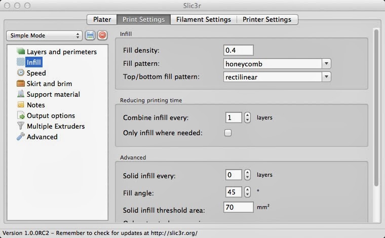
And for the brim, goto "Print Setting" --> "Skirt and brim" --> "Brim width".  Just use 2mm.


I hope you like this work through, next I will go into more detail on each of the options using in slic3r.

Thursday 13 February 2014

What is this 3D slicer program? - Part 1

3D printer firmware is software that control the hardware to create the print, and it mainly GCODE interpreter.   You generate the GCODE by using Slicer program.  Slicer convert 3D object into instruction or GCODE on how to create the object using you printer hardware.

Most common use slicer is:
I never able to get Skeinforge to work on my Mac System, so I'm not the right person to discuss about  it.  When I got started 2010, the only slicer is that are free and commonly use is Slic3r. At that time, I also able to compile Cura for viewing, never really try to use it for production work.  I start to play with KISSlicer when I got started to build delta printer.  Kossel provided KISSlicer configuration file, it make setup much simpler.

Unfortunately it will be a long discussion, and I just finish capture the screenshot, may not be able to finish the post today.  Tomorrow will talk about Slic3r setup and configuration.


Wednesday 12 February 2014

What this 3D printer motor thing?

There is two main type of motor use in 3D printer, servo motor and stepper motor, servo motor is less common because of it higher cost, and servo also consider a close-loop solution, e.g, it know if current location hence better quality.

I'm not going to detail about servo motor, you can get more detail from wiki, as for stepper motor, you just need to know few key property:

Step angle is the single step rotation angle, most type version is 1.8 degree per full step, 200 per revolution.

Micro stepping is the subdivision of the single step, and typical stepper controller support up to 1/16 step, 1/32 is less common, Higher micro step increase the resolution of the printer.

Bipolar or Unipolar is the way the motor is configure.  Below is bipolar internal wiring.


And here is the internal wiring for unipolar.  Unipolar motor can become Bipolar.  typical stepper motor have 4, 6 or 8 wire, 5 wire are less common and require separate controller then the normal version.


Motor size is set by the NEMA standard, the most common size is NEMA17, next is holding torque or holding force of the motor, Z, Y and Z normally require 13.7N-cm/19.4 ozf.in and for gear extruder require 40 N.cm, recently we are seeing increase use gear stepper motor for extruder.

For the most optimize micro stepping, choose motor that have voltage range of 3-5v and current range of 1-1.15A.  It this true for stepper controller that have current-limiting feature such as Pololu A4988.

Shaft size typically 0.5mm diameter.  Make sure you get the correct pulley with the right bore size.

Motor Controller chip provide the control to set the direction and step, it normally allow user to control of the stepping rotation resolution such as full, half, 4th, 8th, 16th and 32 step.  higher the step higher the resolution.    Another thing to take note is the output current, higher the current mean you can drive a bigger motor.

There is a trip-pot allow you to set the desire current.  If you building printer from parts, make sure you check the motor current is setup correctly, test the perfomance of your motor by check if it too running too hot then it maybe over current, also if when you try to hold the rotation of the motor shaft and it skip step, it maybe under current, both case you need to adjust the power using the trip-pot. Be careful not to short the circuit during adjust, else you may burn the controller.

Also in the firmware configuration.h, there a are that section that the step per unit .  You need to adjust this part when you have the correct pulley and stepping.


Tuesday 11 February 2014

What this 3D printer controller board?

Every 3D printer require a controller,  either it a dedicated microcontroller board such as Arduino and Arduino derivative board or your PC.  The main purpose of the 3D printer controller is run software that convert Gcode to electronic signal that drive stepper motor or the control plastic extruder.  Think it as a command interpreter.

Here is the key component of a typical 3D controller board:

  • Computer or microcontroller that run the printer control software, normally this software is call printer firmware.
  • Motor control board for 3D location and extruders.  if you have have more the one extruders then you may need more controller board.  
  • Temperature Sensor for the extruder and heat bed.
  • SDCard support for printing file storing and retrieving.
  • Power on/off switching for Heating as well as fan.
  • X, Y and Z end-stop to tell the software where the printer head is located at start.


Above diagram show an typical arrangement how the part is connected to the controller.  Sensor like temperature is read using A2D (analog to digital convertor).  Normally the heat sensor use is Thermistor, need to be careful on which thermistor you are using, difference thermistor have difference temperature table.  Make sure you are setting the correct table in your firmware configuration file, else you may overheat or underheat you extruder due to wrong temperature reading.  It the most common mistake make by a new builder.

Heating element like resistor, nichrome wire and recently cartridge heater is driven by the microcontroller PWM signal, PWM is very common method of controlling the amount power to a load without incurring losses. Think of it as a method to control temperature and typically the PWM signal is connected to a MOSFET device that act as switch that connect the heating element to the main supply. e.g.12v or 24v, so that it can drive with full power from the main.  Controller also run PID routine for better temperature stability.  There also have a Gcode to help you tune your extruder.

GPIO is use for taking input signal from the X Y and Z start location switch, and to send control signal to motor controller.   Will have a dedicator discussion on the motor controller and motor itself, since it very importance subject that need more clarification.   Your print quality is depended on you motor!!! So be really careful on you Motor configuration.

I leave out feature such as networking and SDcard support, both very nice to feature but really needed for typical operation.


Monday 10 February 2014

What is this I2C PWM breakout board?

In one of my project, I needed more PWM output for servo control, but the board I'm using only have 2 PWM output, which mean I have two choice, either use a software base PWM (slow) or external PWM chip, I decided to go with external chip.

And the most common DIY I2C PWM chip is PCA9685 or TKC5940, and because PCA9685 is have free running feature (does not require constants update from micro microcontroller or CPU), we are going with this chip. 

You can buy prebuilt board such as Adafruit 16-Channel 12-bit PWM/Servo Driver.  But it cost over $15USD and mail to Malaysia will added few more dollar.  And because I such a cheapskate, I wanted to see how can I do to reduce the cost and also not spending a lot of time building my own PCB. 

First is to check if I can buy this chip locally, and Farnell/Element14 does carry them, and it about 9.42RM/2.49USD. Which I think is very reasonably price.

Second thing I do is to see if there is a TSSOP to DIP conversion board, if I can convert the pins to DIP, it make everything simpler, since I can build my own breadboard.  And ebay is your friend, I found 5 pieces TSSOP to DIP28 for $1.66 and free shipping.  Also got myself 50pin Gold plated male pin for $0.25USD.


For cost of $3.33, I have all the needed part, yes, it not as nice as the Adafruit I2C PWM board, but for 1/5 of the cost, I can live with that.

One of the main concern is how the hell are we going to solder TSSOP tiny pins? it so small, the fact is, it really easy to solder them, the trick is to solder all the pins at once and then clean it up later.

Here is the step:

  • Hold down the part to be solder, I used glue.


  • Next is to align the pins, you need a magnifier glass for this.
  • Add solder to the pins, short is ok, will clean up later.

  • Try to remove the excess solder by using your soldering iron as much as possible then use multicore wire and with a lot of solder flux to remove any remaining solder. Just put the multicore wire on top of the shorted area and hold down the soldering iron to transfer the solder to the wire.
  • Once you removed all the solder, you will have a clean and short free board.


From the picture, you can see that you can get really good connection using this simple method.  And it save a lot of money too.

Very importance to visually check the pins to see if there is any shorts, I'm using a 3X magnify glass from Daiso, it only $5RM/$1.5USD.


The whole process only take 20min, and it reduce the cost by 5X!!  It really a wonderful learning. I hope you will try this out too...

Here is some useful information that you can get from datasheet.  Here is the pin information:

   Also here is the application example, I notice that Adafruit board have 220ohm as output protection.  So in  diagram below, you can replace the transistor, led and resistor to single 220ohm, will build the breadboard in my next update:


Sunday 9 February 2014

What is this DIY 3D printer type?


There is many type of DIY 3D printer, basically if divided to printing material and the way printer head and bed is mounted.

Most common DIY 3D printer material is base on plastic filament like ABS or PLA, but there is other type that use powder or light sensitive UV resin.  UV resin base printer currently provide the best print resolution or quality, but the price of the printer as well as the resin is very high.  You can look at the detail from the Reprap 3D printer family tree below:


Since we will be focusing on the most common type of 3D printer that build by DIYer, we will be focusing on filament extruder type 3D printer.

In the filament extruder category, we can further divide the printer type by the way the print head and bed are mounted or move:


The first four type and use XYZ as the base of axis movement or cartesian coordinate system, the delta and polar using difference type of arm movement design. More detail could be found in the Reprap Drive Train wiki.

The way the printer head and bed are design will determine how the printer frame be constructed. Will talk about them in detail when we go into individual printer design discussion.

Next is the printer motion guide and power transmission, early motion guide is normally using linear bearing such as LM8UU and 8MM rod due to the cost, single LM8UU only cost less then 1 dollar, but recently we are seeing move to linear guide as price are getting cheaper, and it provide better accuracy compare to linear bearing, and it less noisy too.   For the power transmission side, it either lead screw or belt base, belt have better speed performance compare to lead screw, but in area that does not need speed like Z axis, it still prefer to use lead screw since it provide highly resolution.  There is two main type of screw design, normal lead screw or ball screw, ball screw normally have better accuracy due to elimination backslash. But price and availability limit it usage in DIY. If you can afford, ball screw really help to improve print quality, and new china supplier seem to reduce the price significantly.

Will continues tomorrow...

Saturday 8 February 2014

What is this DIY 3D printer?

What is this  DIY 3D printer?  I would say it a hobby that build 3D printer for fun,  most of the time is because the builder wanted to create part for his other project, like me, I wanted to to build part for my own coaxial copter design.  Anyway I make a lot of mistake in my choices on how to build the 3D printer.  I hope by sharing my experience, you can avoid the mistakes.

To understand 3D printer, you really need to understand the key component of the printer:

  • Printer frame that hold the stepper motor and print head, you could say it a 3 dimensional plotter. It need to support X, Y and Z direction movement.  Stable frame will improve your print quality.  The frame design normally is the printer design name, by selecting the printer design name, you basically selecting the printer frame.  Reprap printer tree will help you to understand the design history of the frame.

  • Arduino base controller board, it normally have AVR micro-controller, recently we are seeing ARM base controller too, it the brain of the printer that controller all the stepper motor and print head.
  • Firmware that run on the controller board,  normally a GCODE interpreter, GCODE is most commonly used programming language in CNC domain, it have command such as drawing a circle, goto location and some control such as turn on the heating element.
  • Printer head is normally a plastic extruder, it design to extruder plastic in a control way,  it consist of a motor and gear that push the filament in to the hotend, hotend have heating element and temperature sensor use by the software to maintain constant temperature so that you get consistence plastic output from the print head.
  • Print bed is the area where 3D object to be printed, it also provide another very importance function: to hold down the part to be printer. if the part move during print, you print is basically ruin. Holding down printing object is another major issues in 3D printing.  There is a lot of way to secure the object down, like heated bed and Kapton tape.  It an area that need a lot of fine tuning.
  • Stepper motor is the mechanical part that provide the motion, normally you need to select the suitable size, and the stepper motor controller or driver will determine you print resolution, how fine you can print is control by the step.
  • Power supply, depend on the material you plan to print,  you will have difference requirement.  Normally if you plan to print ABS or nylon, you need power supply that can handle over 150W.  
  • PC, you need this to send the GCODE to the printer as well as doing the initial calibration.  with the recent advancement, we are seeing web base controller that allow you to do all the calibration in the printer itself, but still you need to have a host to create the GCODE file.
  • Slicer program, it a program that convert 3D object to GCODE that controller use to create/draw the part in 3 dimension.  Most common support input format is STL.  The most popular 3D slicer is Slic3r.
  • 3D model, you can create them in one of the CAD program or download from site such Thingiverse.
  • Printer calibration, although it not a component of the 3D printer, but it the most critical part of the process.  How well you print come out depend on how well you calibrate your printer.  
Will continue tomorrow to talk about each component in detail.


Friday 7 February 2014

Extruder Hotend

There is two thing I really hate about DIY 3D printer, one is calibration and another is the hotend.  Hotend really is the most painful part of DIY 3D printer in my experience.

Why extruder is so painful? Because the most common use hotend is j-hotend, and this hotend easily melted, if melted, there is no easy way of fixing it, that why most of the new design is base on all metal design to avoid melting... arr....

Another reason is because it take weeks to get it replace since I live in Malaysia.  Also when I got start I never know that it have this "melting" problem, and I should have order few backup, but since I'm a cheap, I only order one, that was a big mistake...

Currently my deltabot also have the melted j-hotend, I only notice it recently,  oh well, will order one soon, it really take away my fun experience....

Anyway, in the process of search for better hotend, I come to across stepextruder that have all most all metal part except it have ptfe tube between hotend connection, which I think it a good thing. Another great thing about this design is all the part are serviceable, I mean it can be unscrew and clean if you encounter jam.  Trust me, this is a very good feature when you got started..


Above is the picture of my new stepextuder, but I think I got the wrong screw size & type, it not fitting as I would like, will need to replace them.  But I really like the design, and I think I will have less problem with this compare to j-hotend(I'm hoping), will start testing once I got my screw replace...

I'm also trying to start testing this extruder with nylon, but I make a mistake of getting a 2.5mm nylon instead of 1.75mm, will need to replace them on monday, since it 9th of chinese news in penang, most of the Chinese shop will be close.

I'm also thinking building a RC glider, I have this book that show how to build RC plane using foam, and I have it for years and never really try out the process.  Here is the book that I talk about.


 It really a good book, I alway wanted to try the process, also you can build an CNC foam cutter if you want automation. CNC version not that complicated, I have most of the part already. Not sure if I have time...

  Here is my quick glider drawing after looking at Falcon UAV, I plan to enter it to CAD program later when my PC is back from shipment.


It really look amazingly simple, but I'm still having hard time figuring out how to connect flip  to the servo for controlling the glider.

That all for today....

Thursday 6 February 2014

After long time

I'm thinking starting to write daily blog from today onward.

So what am I doing recently, not much, spend more time in reading then actually doing anything, but now I'm back to my home town and start to restart some of the project.

I have few project that I wanted to finish but never got the chance to finish them.  Here is my small list of diy project:


  1. 3D printer for Nylon.  I wanted strong part for my project.
  2. Finish my kossol 3D printer, currently the print head is having so much issues.
  3. Production 3D printer. The one I have now require a lot of tuning after each print...
  4. Microscope with DIC adopter.
  5. Drone -- Quacopter and sailplane 
  6. Go-Kart
  7. Writing book 
Hopefully I can start daily blog update from now onward until I have enough material for a book.